2024-11-10 / Bairui SU
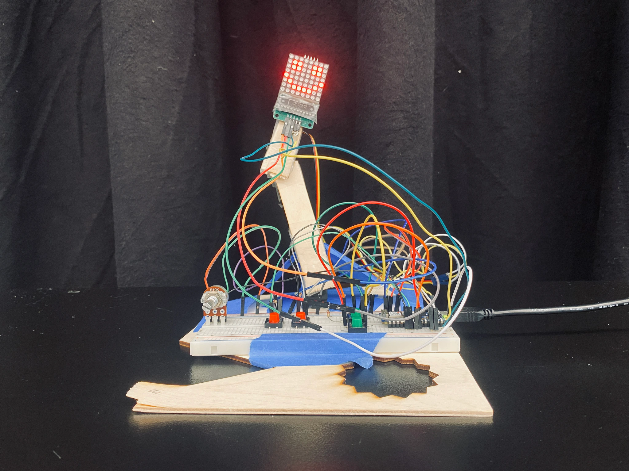
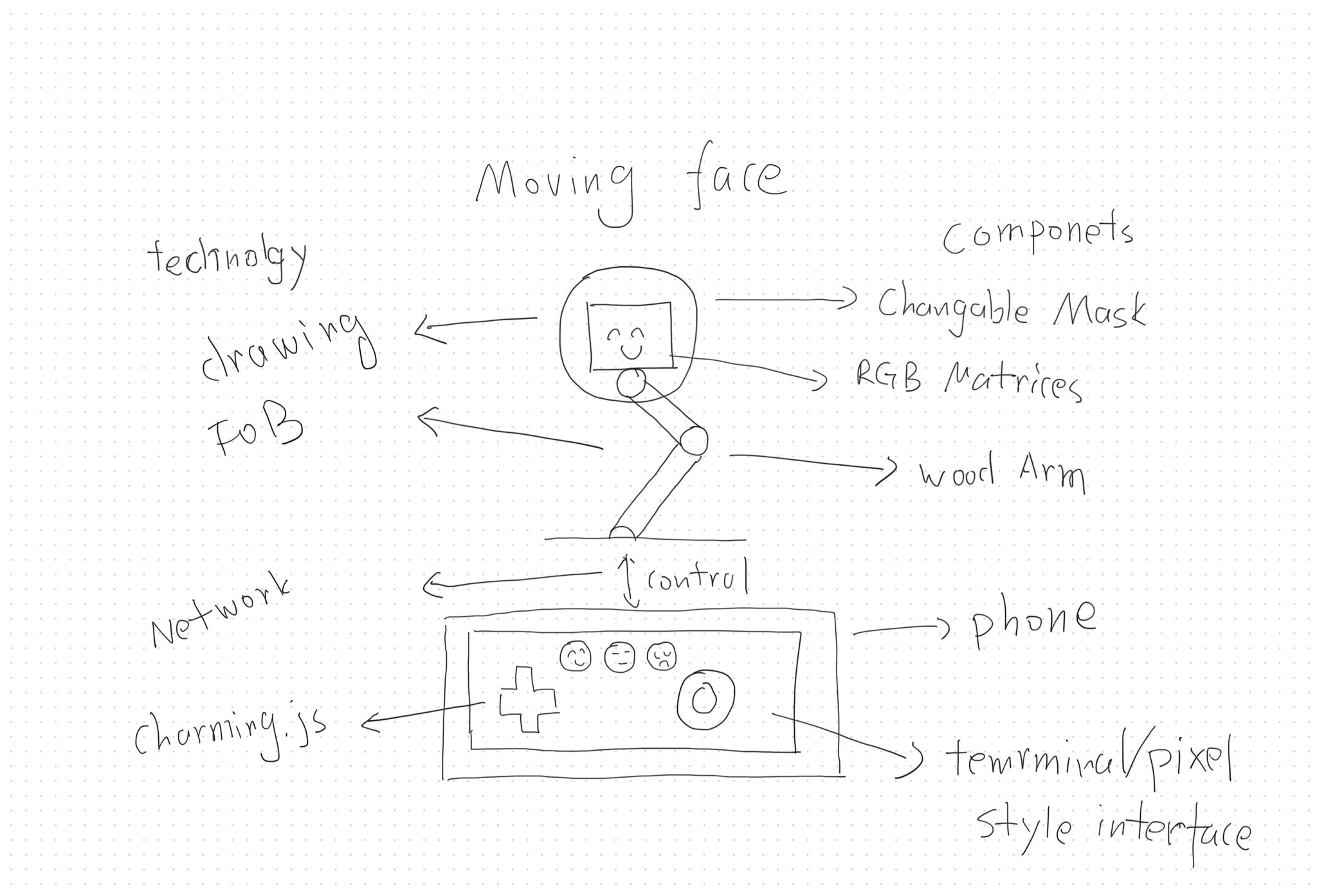
For the midterm project, I finally made a simple robotic arm with a smiling face. I named it Frankenstein I, symbolizing a creature crafted from a collection of discarded materials.
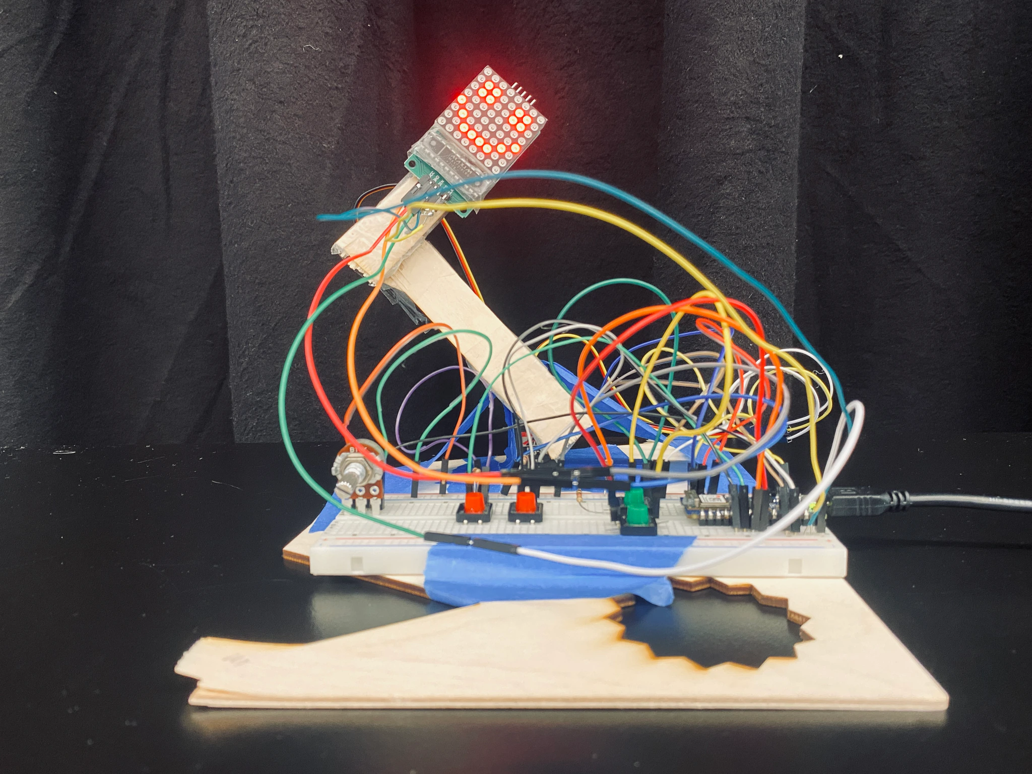
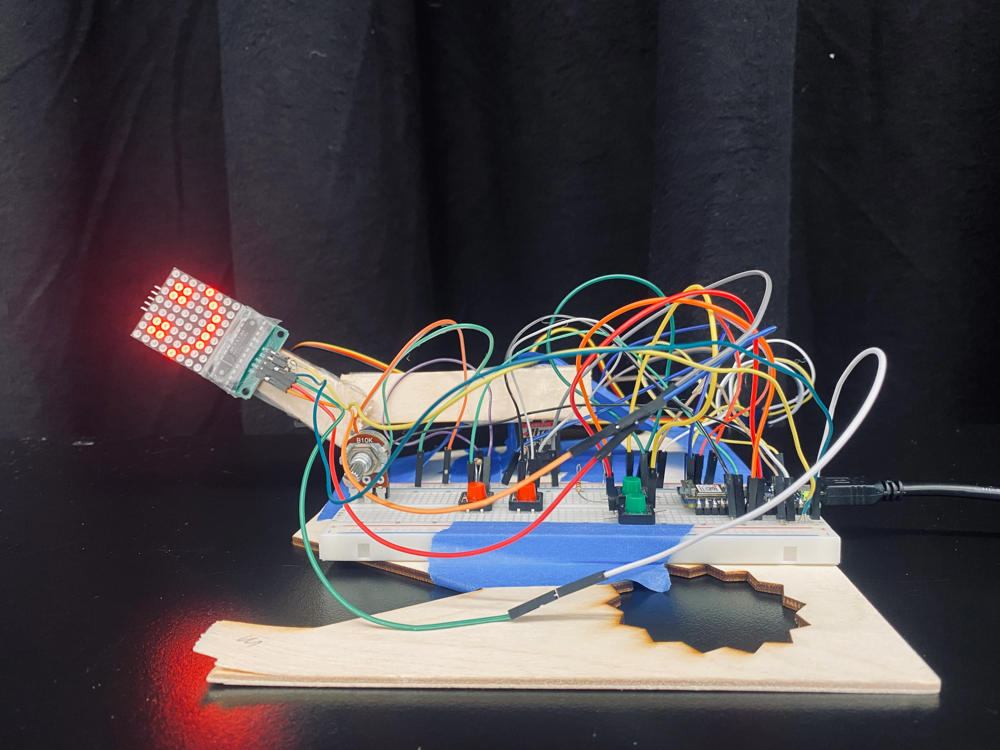
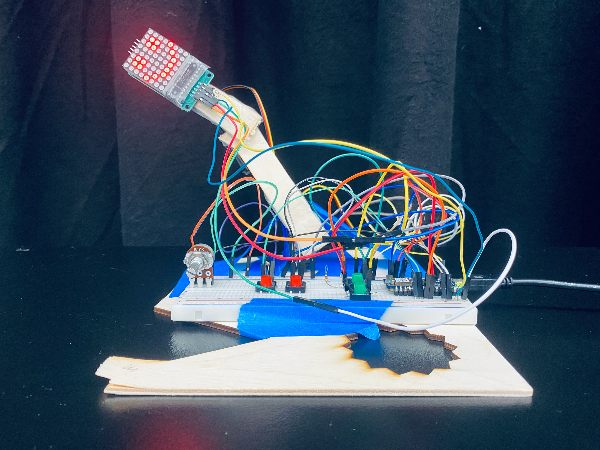
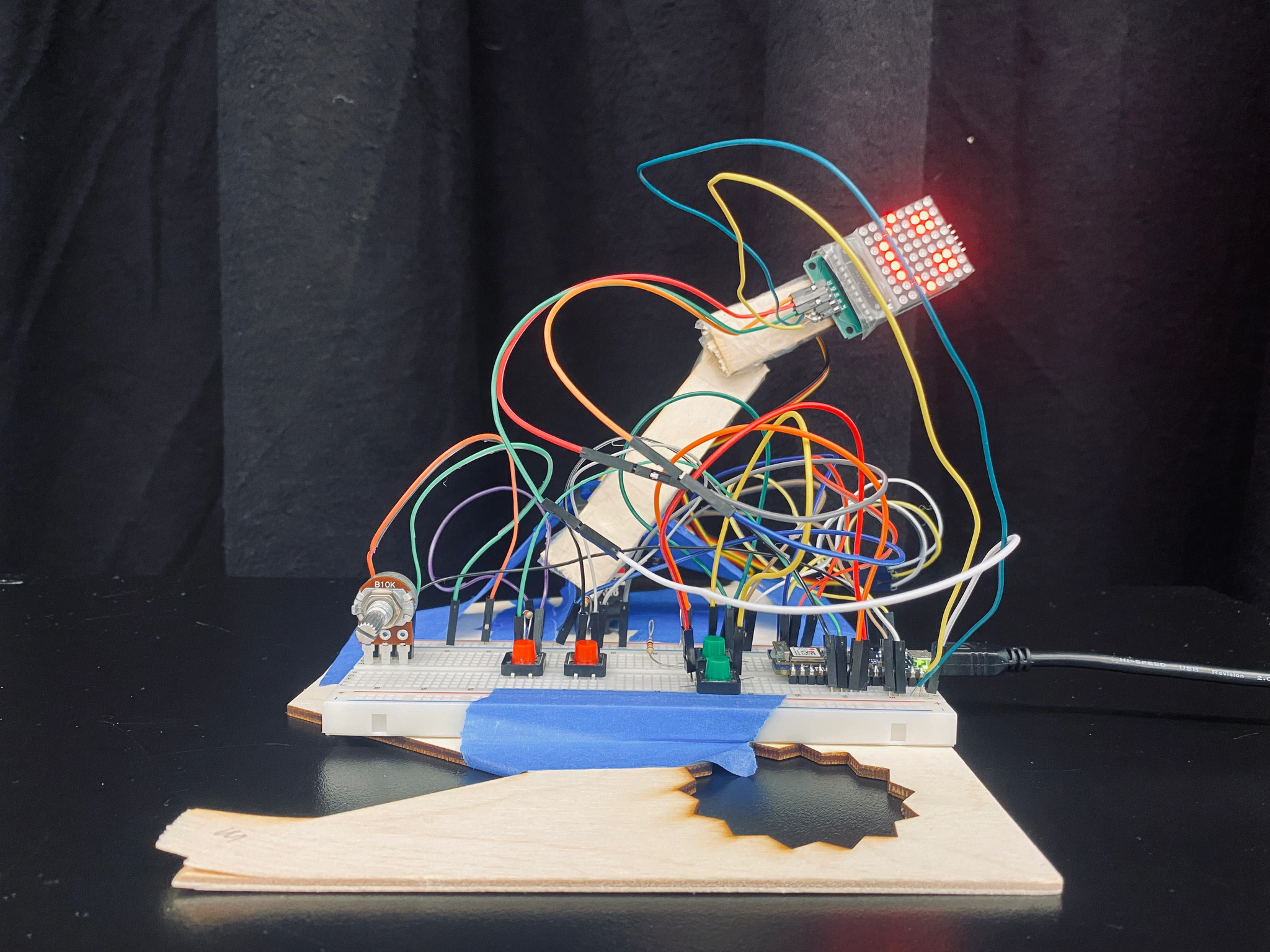
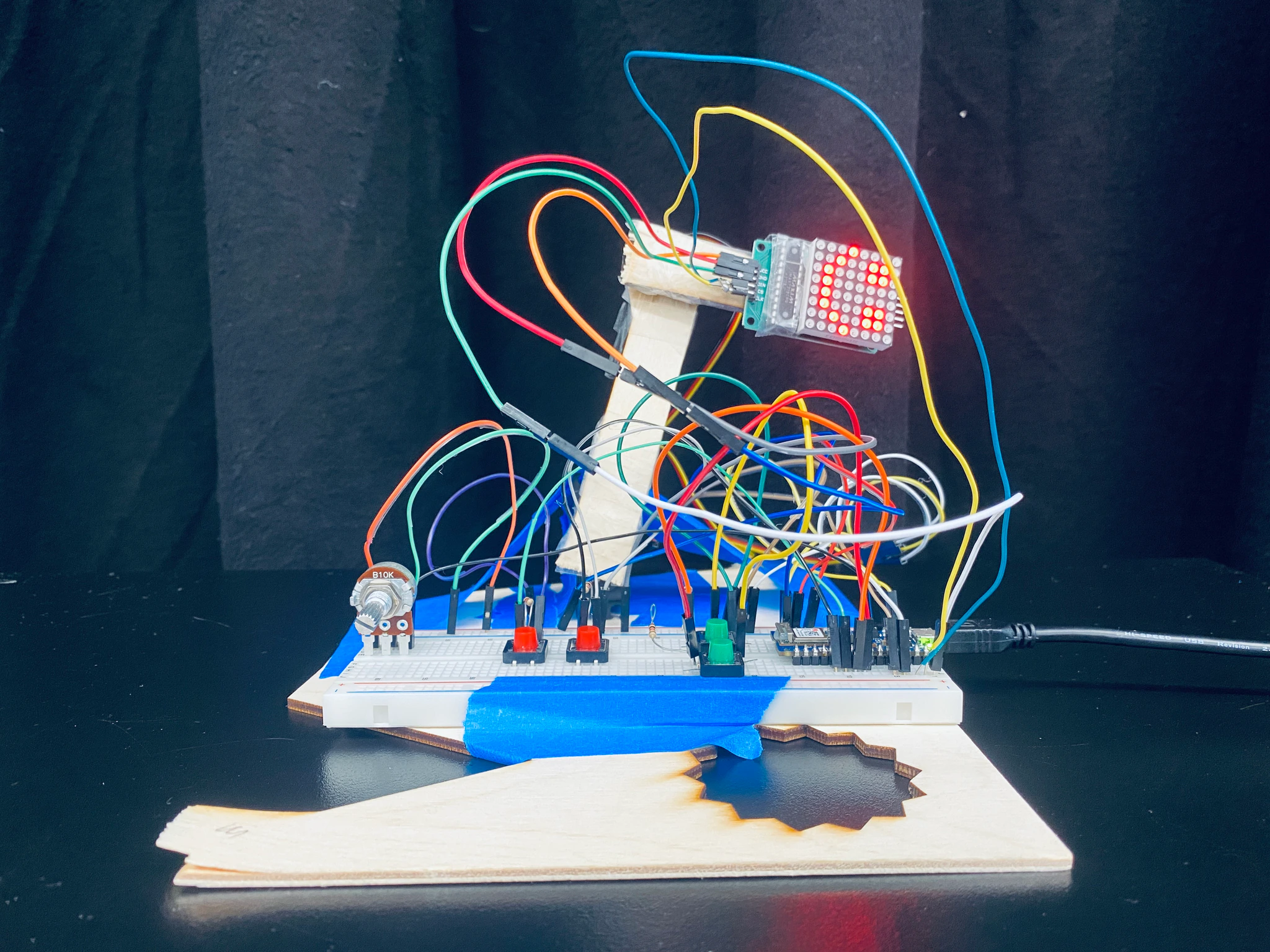
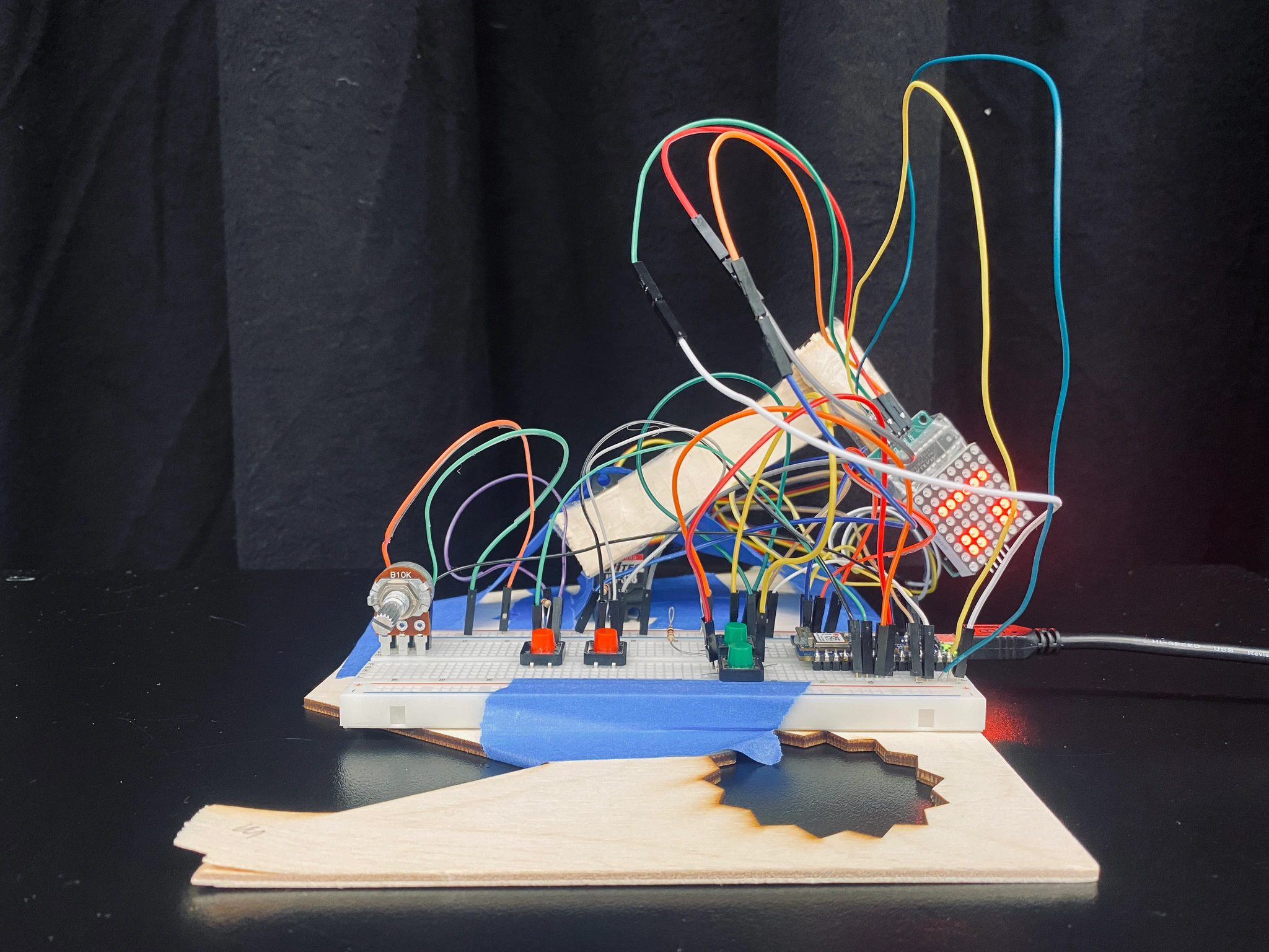
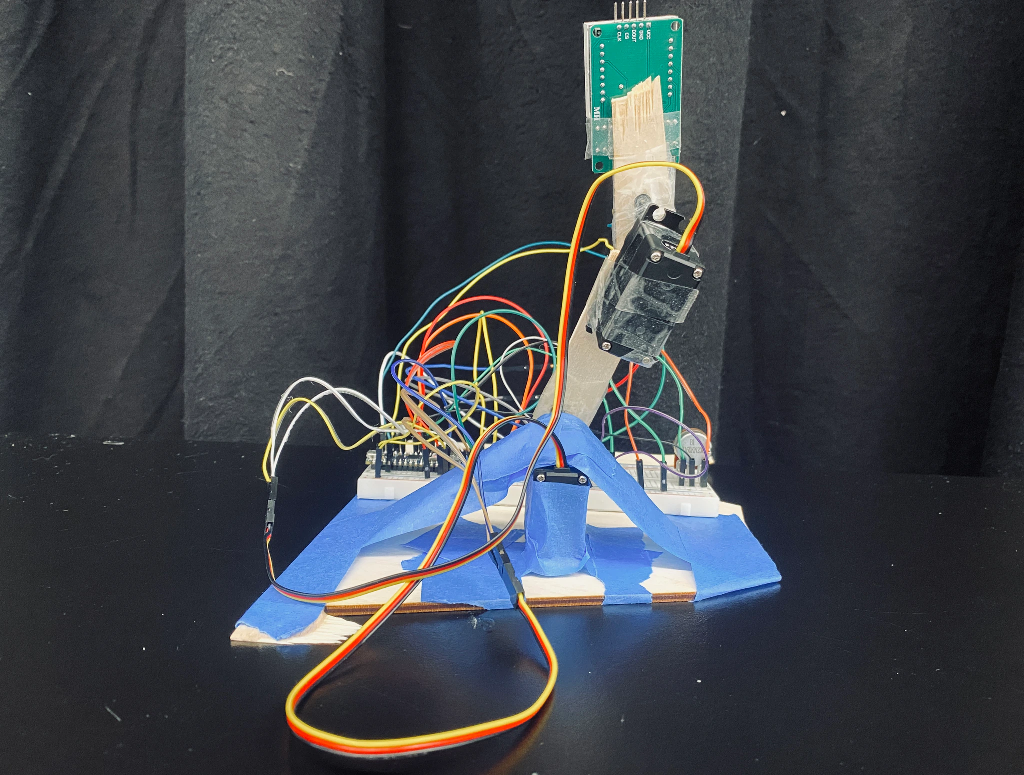
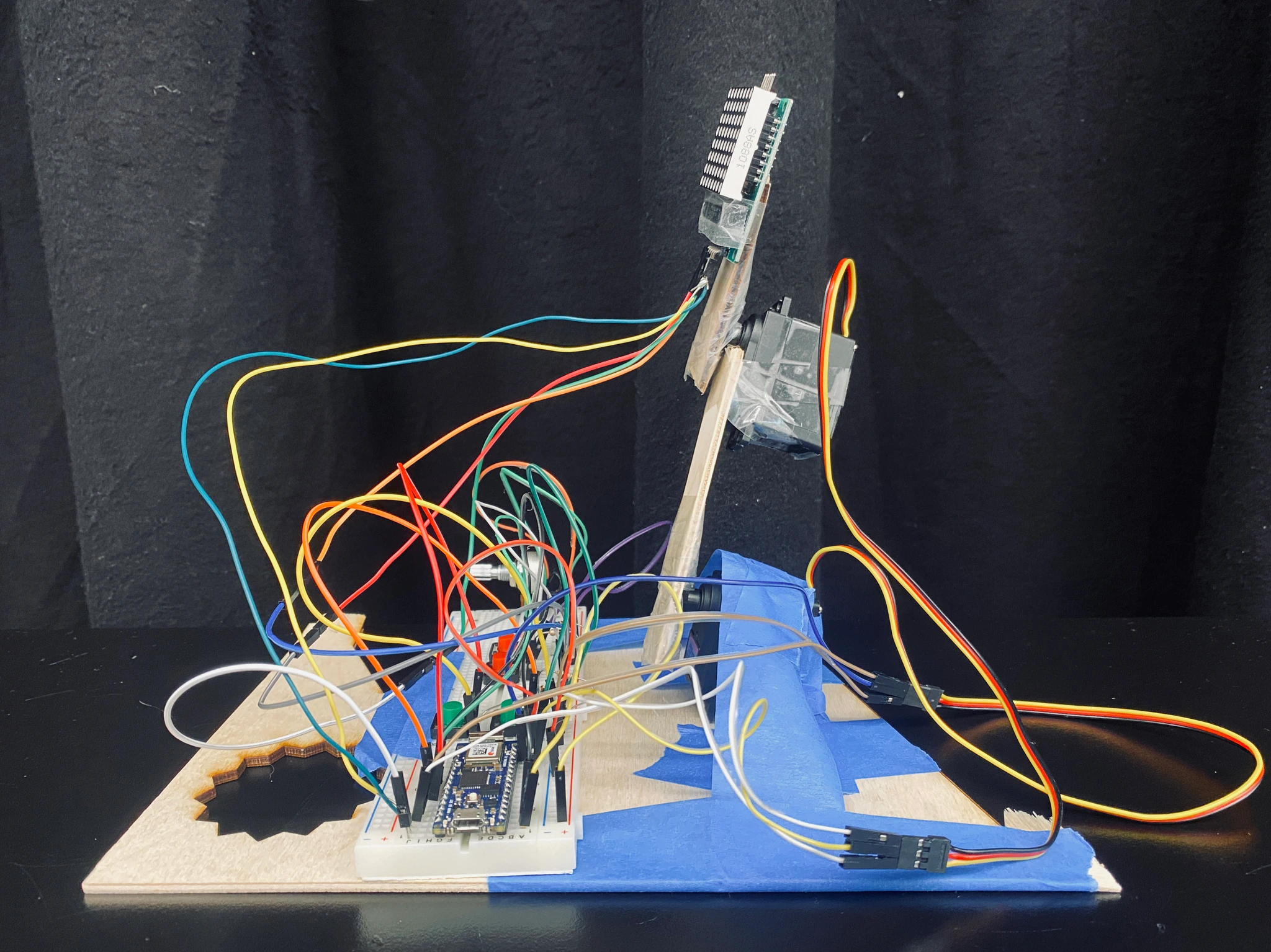
Four pushbuttons control the arm’ position in Cartesian space, while a potentiometer to adjusts its moving speed. When the arm moves outside its workspace, the face turns sad, smiling again when it returns to a valid position.
When designing this project, I had three objectives:
- Keep it as simple as possible
- Apply what I’ve learned so far
- Make it small but meaningful
This is why I used only basic components and assembled them with tap, without neatly wrapping the wires. But I’m glad that I incorporated digital input, analog input and inverse kinematics into real-world project. In the end, it is small but it is a robotic arm!
Here is the source code of this project. If you like, please give it a star! Next, I’ll briefly explain the whole process and share some thoughts.
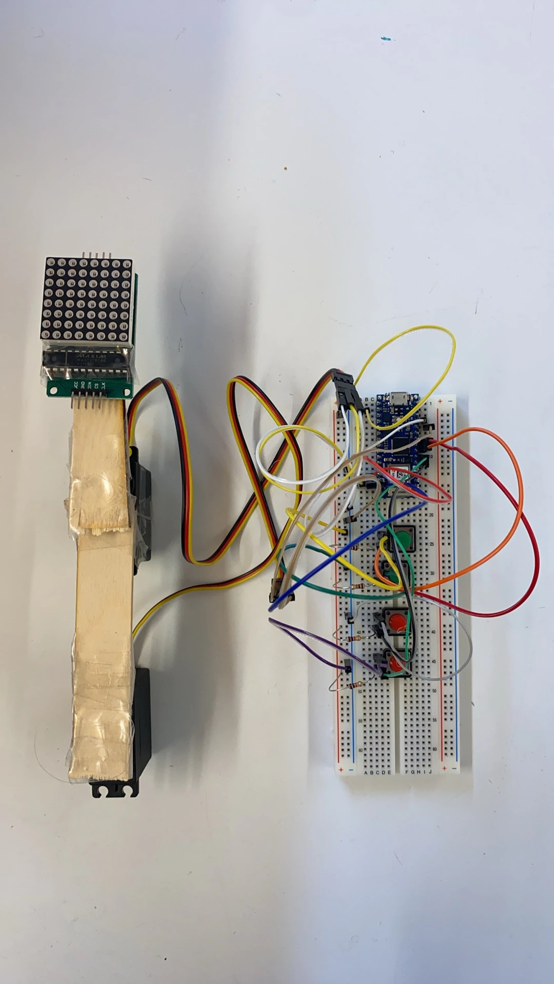
Preparing the components
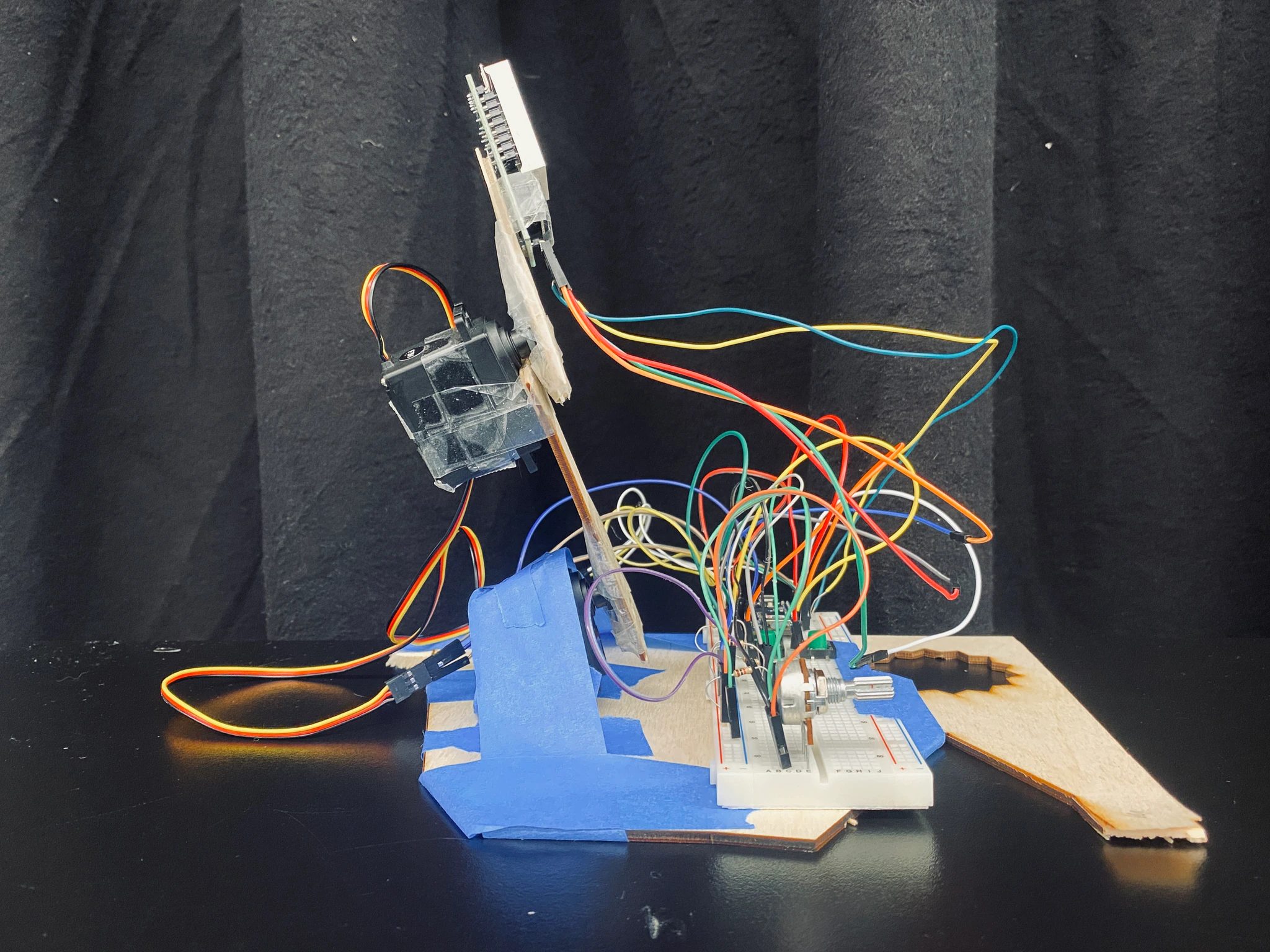
Theses are the main components needed for this project, which are very basic and easy to obtain. I found a discarded wood and split it into two sticks and a wooden base with my bare hands. After that, I borrowed some wires, a motor servo and a LED Matrix with some classmates. Then I was ready to go!
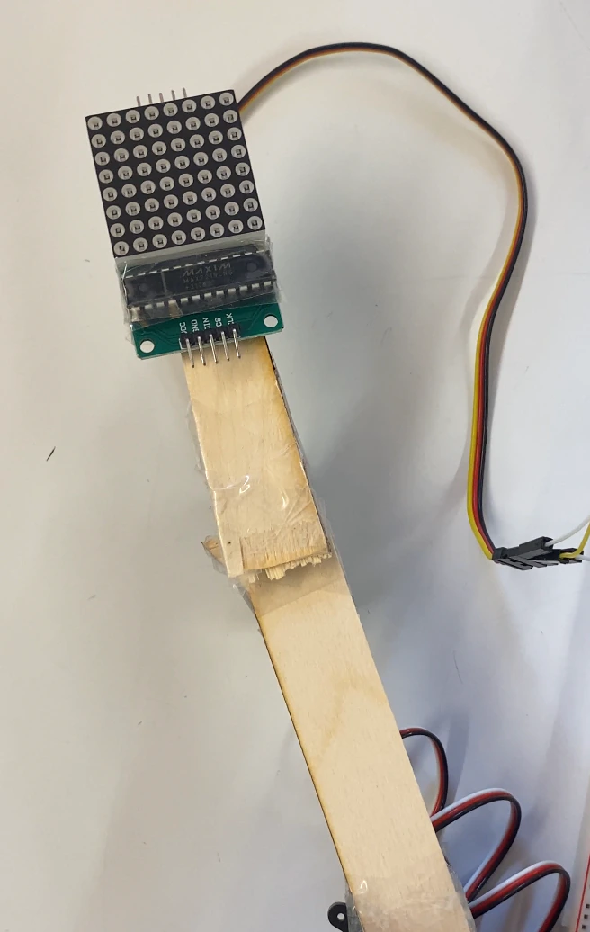
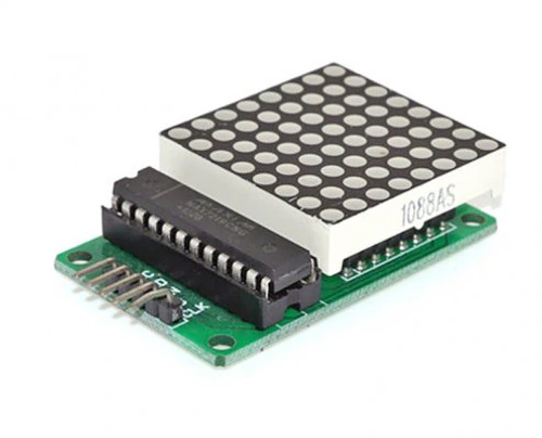 LED Matrix x 1
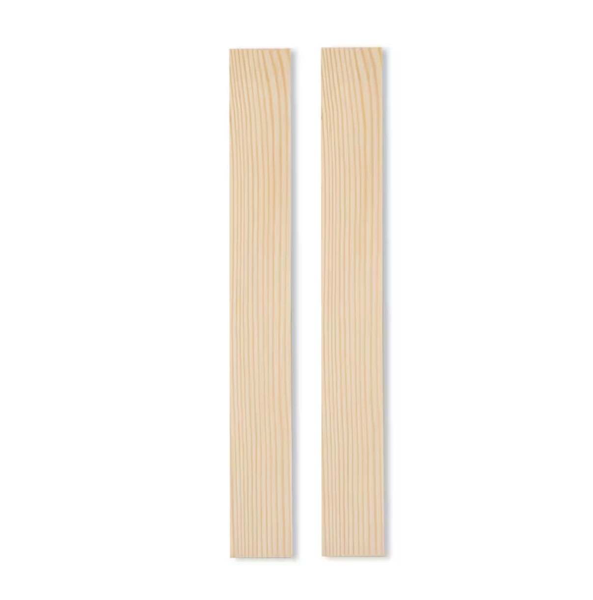 Wood stick x 2
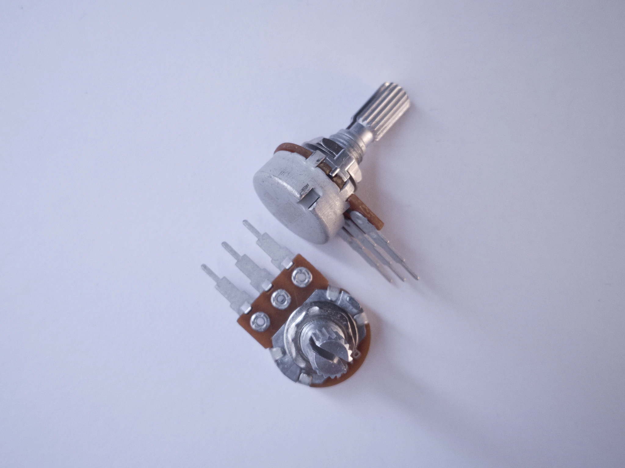 potentiometer x 2
 Serve motors x 2
 Wooden base
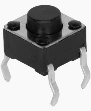 pushbuttons
Assembling components
I decided to it assemble the components only using tapes, thinking it would be easier and more flexible. After obtaining some tape from the shop, I began the assembly process. While taping wasn’t as simple as I’d expected, I’m satisfied with the end result. I’m sorry for using half the double-sided tape!
Moving in the joint space
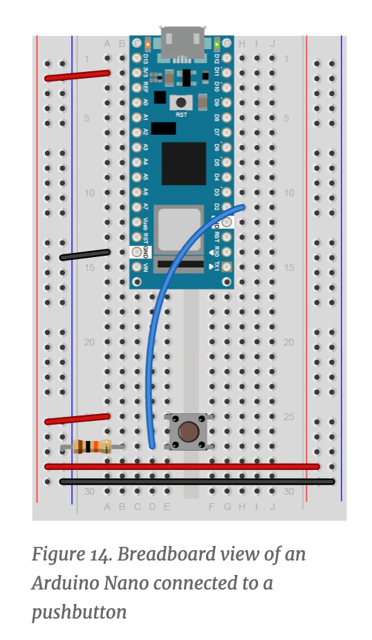
After assembling all the components, I first attempted to make the arm move in joint space. So I took reference from the digital input lab in week2 to wire four pushbuttons for controlling the movements.
I implemented a updateValueOnButtonPress function to update the specific value when corresponding button is pressed.
#define RIGHT_BUTTON_PIN 2
#define LEFT_BUTTON_PIN 3
#define UP_BUTTON_PIN 4
#define DOWN_BUTTON_PIN 5

float leftX = 0;
float rightX = 0;
float downY = 0;
float upY = 0;

void setup() {
  pinMode(RIGHT_BUTTON_PIN, INPUT);
  pinMode(LEFT_BUTTON_PIN, INPUT);
  pinMode(UP_BUTTON_PIN, INPUT);
  pinMode(DOWN_BUTTON_PIN, INPUT);
}

void loop() {
  updateValueOnButtonPress(LEFT_BUTTON_PIN, prevLeftButtonState, leftX, moveSpeed);
  updateValueOnButtonPress(RIGHT_BUTTON_PIN, prevRightButtonState, rightX, moveSpeed);
  updateValueOnButtonPress(UP_BUTTON_PIN, prevUpButtonState, upY, moveSpeed);
  updateValueOnButtonPress(DOWN_BUTTON_PIN, prevDownButtonState, downY, moveSpeed);
}

void updateValueOnButtonPress(int pin, int &prevButtonState, float &value, float moveSpeed) {
  int buttonState = digitalRead(pin);
  if (buttonState == prevButtonState && buttonState == LOW) value += moveSpeed;
  prevButtonState = buttonState;
}
After obtaining the input movements, I drove the two motors directly based on the movements.
#include "Servo.h"

#define UP_SERVO_PIN 9
#define DOWN_SERVO_PIN 8

Servo upMotor;
Servo downMotor;

void setup() {
  upMotor.attach(UP_SERVO_PIN);
  downMotor.attach(DOWN_SERVO_PIN);
}

void loop() {
  // ....
  if (millis() - prevMoveTime > 20) {
    downMotor.write(servoAngle1);
    upMotor.write(servoAngle2);
    prevMoveTime = millis();
  }
}
Here is the result:
Lighting the LED matrix
The next step was to give the arm a face! This was relatively straightforward pretty because I asked the Chat GPT for guidance on programming a LED matrix. I used a two-dimensional byte matrix to store three expressions: smile, neutral, and sad. There will be more in the future!
#include <LedControl.h>
#define DIN_PIN 12
#define CS_PIN 10
#define CLK_PIN 11
LedControl lc = LedControl(DIN_PIN, CLK_PIN, CS_PIN, 1);
byte expressions[8][8] = {
{ B00000000, // Smile Face!
B01100110,
B01100110,
B00000000,
B10000001,
B01000010,
B00111100,
B00000000 },
// ...
};
void setup() {
lc.shutdown(0, false);
lc.setIntensity(0, 8);
lc.clearDisplay(0);
displayFace(expressions[prevFaceIndex]);
}
void displayFace(byte *face) {
lc.clearDisplay(0);
for (int i = 0; i < 8; i++) lc.setColumn(0, 7 - i, face[i]);
}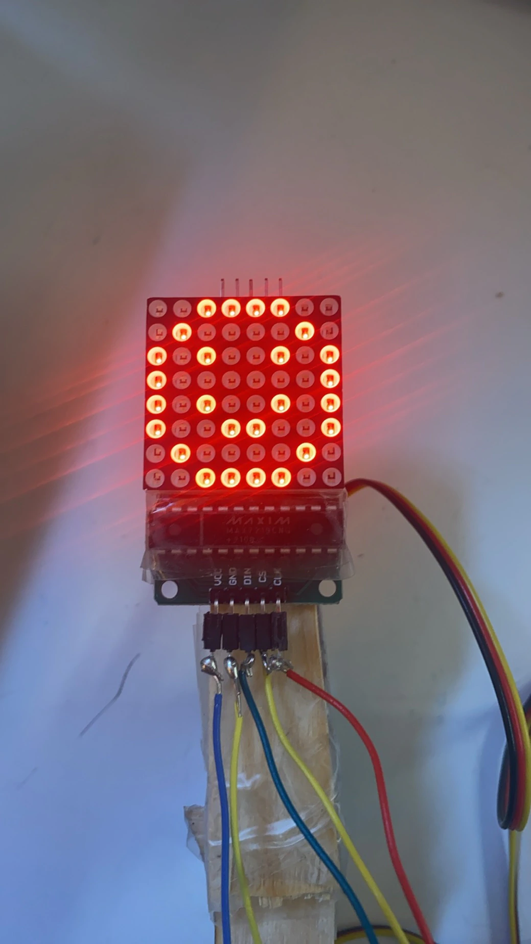 The first version of smile
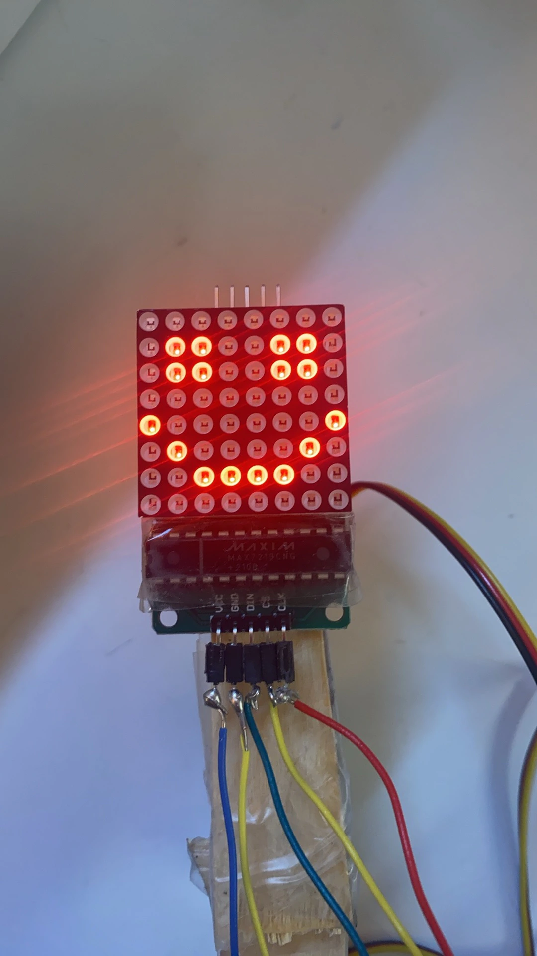 The final version of smile
Moving in the Cartesian space
Then came the hardest and most time-consuming part of this project: applying inverse kinematics to move the arm in Cartesian space instead of joint space. The math itself is not difficult; it only takes several lines of code:
/**
 * Compute the angles (in radians) for given position and lengths.
 *
 * px: the x of the expected position
 * py: the y of the expected position
 * a1: the length of the bottom arm
 * a2: the length of the up arm
 *
 * angles[0]: the angle for the bottom arm relative to ground
 * angles[1]: the angle for the up arm relative to the bottom arm
 */
float *inverseKinematics(float px, float py, float a1, float a2) {
  float *angles = new float[2];

  float c2 = (px * px + py * py - a2 * a2 - a1 * a1) / (2 * a1 * a2);

  // Out of range.
  if (c2 > 1 || c2 < -1) {
    angles[0] = INVALID_POSITION;
    angles[1] = INVALID_POSITION;
    return angles;
  }

  float s2 = -1 * sqrt(1 - c2 * c2);
  float t2 = atan2(s2, c2);
  float t1 = atan2(py, px) - atan2(a2 * s2, a1 + a2 * c2);

  angles[0] = t1;
  angles[1] = t2;
  return angles;
}
However, C++ proved challenging to me! After uploading my code at certain points, it failed to upload again! The same issue happened when I tried using another Arduino! After I spending about 3 hours troubleshooting, I discovered the problem: I didn’t freed the pointer after declaring an array pointer!
void loop () {
  float* angles = inverseKinematics(/* .... */);

  // !!! Important
  // Without this line, you'll screw your Arduino!
  delete[] angles;
}
This might be due to writing too much JavaScript… Additionally, I measured the length of the two sticks with rulers to obtain the necessary parameters for inverse kinematics.
Detecting invalid workspace
Robotics arms have limitations, they can only operate within a specific workspace. To enhance user experience, I decided to notify users when the arm detects an invalid workspace. I chose to convey this by changing the arm’s face to a sad expression.
A important thing is that the calculated workspace is the ideal workspace. The real workspace is the subspace of the ideal workspace, so it’s crucial to detect all invalid situations! Failing to do so result int discrepancies between the virtual and real positions of the arm, leading to unexpected behaviors.
void loop() {
  float *angles = inverseKinematics(currentX, currentY, a1, a2);
  float t1 = angles[0];
  float t2 = angles[1];

  if (t1 == INVALID_POSITION
      || !isValidServoAngle(servoAngle1)
      || !isValidServoAngle(servoAngle2)
      || currentY < 0) {
    faceIndex = 1;
    rightX = prevRightX;
    leftX = prevLeftX;
    upY = prevUpY;
    downY = prevDownY;
  } else {
    faceIndex = 0;
    // ...
  }

  if (prevFaceIndex != faceIndex) displayFace(expressions[faceIndex]);
  prevFaceIndex = faceIndex;
}
Controlling speed
Finally, I planned to control the speed with a potentiometer, referencing the analog input from Lab 2 in Week 2:
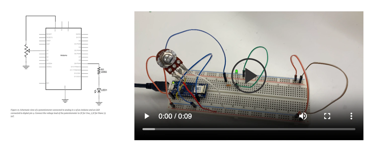
It seemed simple at first, but it spent more time than I expected. I used the built-in map function, but always only got the minimal move speed!
float maxMoveSpeed = 0.004;
float minMoveSpeed = 0.002;
float moveSpeed = (minMoveSpeed + maxMoveSpeed) / 2;

void loop() {
  float analogValue = analogRead(A0);

  // 0.002 all the time!
  moveSpeed = map(analogValue, 0.0, 1100.0, minMoveSpeed, maxMoveSpeed);
  moveSpeed = constrain(moveSpeed, minMoveSpeed, maxMoveSpeed);
}
Finally I found that all the parameters for map should be long...
long map(long in, long in_min, long in_max, long out_min, long out_max) {
}
So I implemented a float version myself. I indeed write too much JavaScript!
float maxMoveSpeed = 0.004;
float minMoveSpeed = 0.002;
float moveSpeed = (minMoveSpeed + maxMoveSpeed) / 2;

void loop() {
  float analogValue = analogRead(A0);
  moveSpeed = mapFloat(analogValue, 0.0, 1100.0, minMoveSpeed, maxMoveSpeed);
  moveSpeed = constrain(moveSpeed, minMoveSpeed, maxMoveSpeed);
}

float mapFloat(float value, float domainMin, float domainMax, float rangeMin, float rangeMax) {
  if (domainMin == domainMax) return rangeMin;
  return rangeMin + (value - domainMin) * (rangeMax - rangeMin) / (domainMax - domainMin);
}
Discussions
In a nutshell, I’m pretty satisfied with what I’ve made. I believe I achieved all three objectives. I’m excited to apply inverse kinematics that I learned in the Foundation of Robotics class. Putting theory to practice is always very cool.
Thanks to Danny for suggesting I simplify my project. The final design is much easier compared to my previous ones. This allowed me to spend less time (four nights) and focus on the most important things!
 Version 1
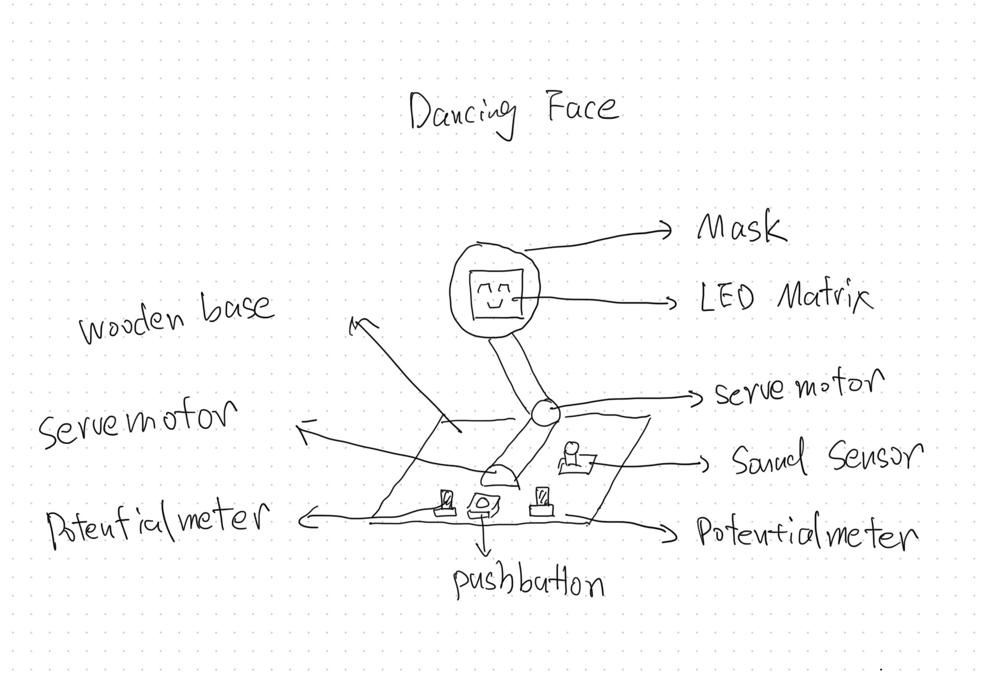 Version 2
One important lesson I learned is to pay attention to C++ and not take dynamic programming languages for granted.
Some might feel sorry for Frankenstein I because it does not look good, but I’m pretty fine with it. It reminds me of Mark I—the first version of Iron Man’s suite. Though created from low-quality materials and looking rather shabby, it saved Iron Man’s life and marked a beginning of a legend!

Frankenstein I is my first tiny robotic arm. I hope it is a good starting point for my journey in physical computing. However, I need collaboration next time!